Receiver development
Consider the passive antenna format for a receiver design with a separately planned RF chain. Include external amplification, cable losses and receiver input requirements in the test arrangement.
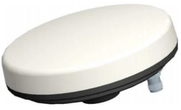
Passive broadband GNSS antenna
For engineering signal-relay and receiver-debugging setups. This passive antenna is not an active replacement: the complete RF chain must be reviewed for the intended test environment.
TDXL-BA810 is a passive broadband GNSS antenna with a TNC-K connection. Its listed frequency range is 1164–1300 MHz · 1520–1615 MHz. Select it together with the receiver and any separate amplification, rather than using active-antenna assumptions.
| Listed signal selection | BDS B1I/B1C/B2a/B2b/B3I · GPS L1/L2/L5 · GLONASS G1/G2 · Galileo E1/E5a/E5b/E6 |
|---|---|
| Operating frequency | 1164–1300 MHz · 1520–1615 MHz |
| Impedance | 50 Ω |
| Polarization | RHCP |
| Maximum antenna gain | ≥5 dBi |
| Axial ratio | ≤3 dB |
| Horizontal coverage | 360° |
| Output VSWR | ≤2:1 |
| Operating temperature | −40°C to +80°C |
| Storage temperature | −45°C to +85°C |
| Humidity, non-condensing | 95% RH |
| Connector | TNC-K |
| Weight | ≤350 g |
| Mounting interface | 5/8-11 · 10–12 mm |
Start with the measurement task, then match the receiver, antenna format and installation. These project contexts help define the configuration to evaluate.
Consider the passive antenna format for a receiver design with a separately planned RF chain. Include external amplification, cable losses and receiver input requirements in the test arrangement.
For signal-relay or receiver-debugging work, specify the purpose and complete receive path. Evaluate the antenna within the planned test equipment rather than as a drop-in substitute for an active survey antenna.
List the receiver model, required GNSS signals and correction method. Match these against the model’s signal selection; a shared constellation name alone does not establish support for every signal.
Plan any required amplification separately. Review receiver bias/DC handling and input protection with the complete circuit; do not apply an active antenna’s power assumptions to this passive model.
Specify cable type, length and the exact mating connector. Review cable losses with the receiver input range and any amplification in the RF chain. Antenna gain alone does not define a maximum cable length.
Include the mounting drawing, orientation and available clearance. For an embedded assembly, include the enclosure and cable exit; for an external antenna, include the support and exposed connections.
Compare the actual signal selection and installation format, not the model number alone.
Broadband active external GNSS antenna. Compare the external active format by signals, power requirements and connector before selecting the mounting arrangement.
Civil multi-band active external GNSS antenna. Compare the external active format by signals, power requirements and connector before selecting the mounting arrangement.
Broadband active embedded GNSS antenna. Compare an embedded MCX assembly when the antenna must sit inside your equipment enclosure; include its installed clearance.
The antenna is one part of the positioning system. RTK operation and accuracy depend on the receiver, correction data, installation and operating conditions. Specify the full system and accuracy target when requesting a model recommendation.
Compare the exact signals, antenna-port electrical requirements and mating connector. Review the complete RF gain and cable losses with the receiver’s input range. A matching connector alone is not enough to select an antenna.
Send the model, receiver, required signals, cable length, connector, mounting drawing and quantity. Include calibration or environmental requirements and your sample evaluation schedule so the configuration can be discussed before ordering.
It is not a direct replacement for an active antenna. TDXL-BA810 is passive, so amplification, cable losses and receiver bias handling must be planned as a complete RF chain. Compare active models if your receiver expects a powered antenna assembly.
Get a Quote
Share your receiver model, bias voltage, required signals, cable length, connector, enclosure and quantity. We can review deeper customization on the existing platform; feasibility is confirmed for each project.