The active vs passive GPS antenna decision starts with the receiver and the RF chain. An active antenna includes a powered low-noise amplifier (LNA); a passive antenna does not. Choose the arrangement that meets the receiver’s power and RF-input requirements after installation—not the one with the larger gain number.
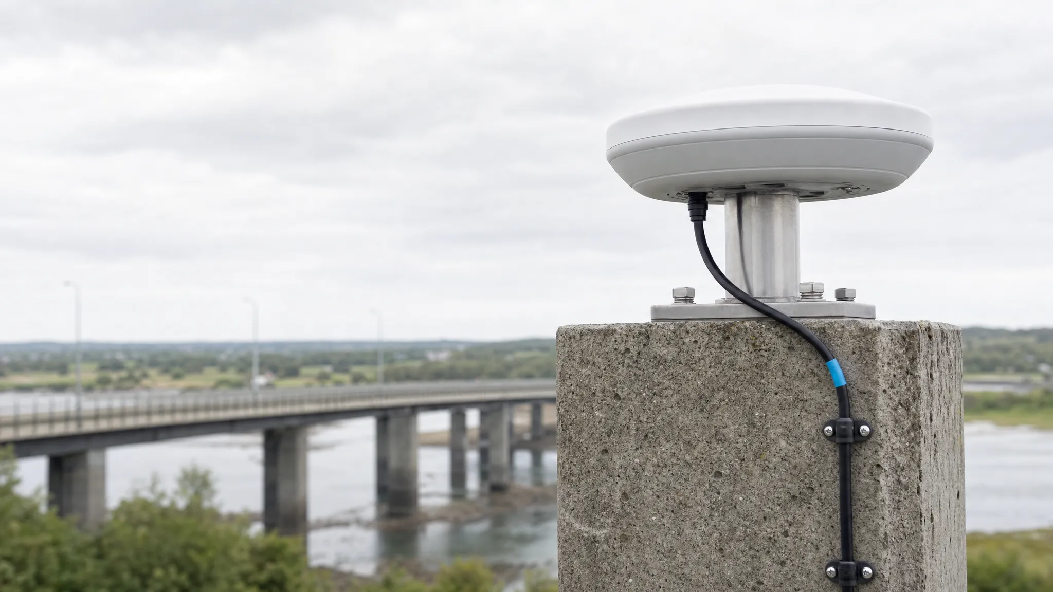
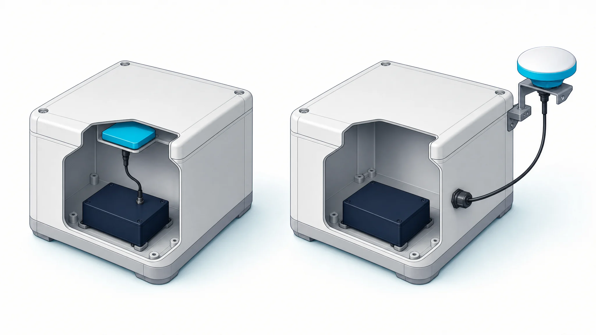
A roof-mounted antenna connected through coax and a small antenna beside a receiver module present different design problems. Both receive satellite signals. Neither an “active” label nor a physically matching connector establishes that the proposed antenna will work with your equipment.
For a device OEM or technical buyer, the useful result is a documented match: required signals, supported antenna architecture, power delivery, gain and loss, and an installation that can be evaluated on samples.
Active vs passive GPS antenna: what actually changes?
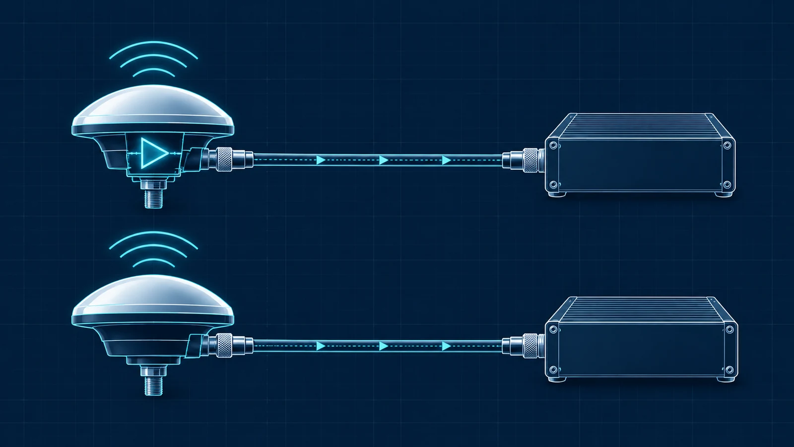
The distinction concerns the antenna assembly’s electronics, not whether it sits inside or outside the device. An active assembly has an integrated LNA; a passive assembly leaves amplification to the receiver or another part of the RF chain. Taoglas’s active/passive GNSS explanation describes this hardware distinction.
| Check | Active antenna assembly | Passive antenna assembly |
|---|---|---|
| Amplification | Includes a powered LNA | No integrated powered LNA |
| Power | Requires its specified supply | No LNA supply at the antenna; other RF stages may need power |
| Cable position | Much of the feedline may be after the first LNA | Feedline may be before the first LNA |
| Receiver match | Check supply and permitted external gain | Check that the receiver or designed front end supports this arrangement |
| Main integration trade-off | Power delivery and gain management | Loss before amplification and front-end design |
| Positioning accuracy | Not established by the label | Not established by the label |
A passive element followed by a board-mounted LNA is still a powered receiving system. Conversely, an embedded antenna can already include an LNA. Keep active/passive, embedded/external and single-/multi-band as separate questions when reviewing a quotation.
Check the receiver’s bias supply before choosing either
Start with the exact receiver module or finished device, including its hardware revision and relevant configuration. “GPS antenna port” is not a complete electrical specification.
For an active candidate, establish four things:
- Supply source: does the receiver provide antenna power, or does the design need a separate supply?
- Voltage at the antenna: is the delivered voltage within the antenna’s operating range after the DC path’s voltage drop?
- Current capacity: can the supply support the antenna and any powered inline equipment under the specified operating conditions?
- Power route: do cables, adapters, splitters and protection components pass or block DC as intended?
An RF signal path can be continuous while its DC path is not. A component’s RF insertion-loss specification does not establish its power-routing behavior. Record both rather than assuming the receiver will power everything attached to the coax.
For a passive candidate, check the permitted DC condition at its connector and the receiver’s instructions for passive operation. Do not assume that “no power required” means an unknown bias supply can remain connected. Depending on the hardware, the correct arrangement may require disabling antenna bias or an appropriately specified DC block.
NovAtel’s OEM7 low-input-gain guidance illustrates why equipment selection must account for amplifier location, current demand and the supply arrangement. Its stated electrical limits apply to the documented OEM7 configuration, not every GNSS receiver.
Compare losses before and after the first LNA
Write down the receive path in physical order. Two designs can contain the same cable and amplifier yet place them differently:
- Antenna-mounted amplification: receiving element → LNA → cable → receiver.
- Receiver-side amplification: receiving element → cable → LNA → receiver.
These are simplified RF paths, not circuit schematics; matching, filters and protection belong in the actual design review.
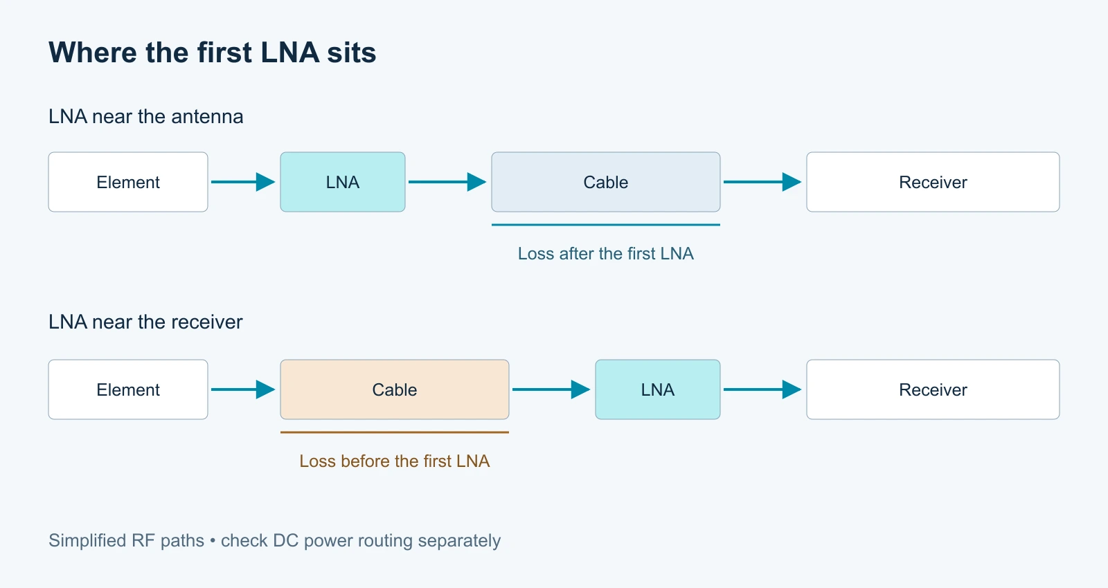
Loss ahead of the first LNA is particularly important to system noise performance. Adding amplification after that loss can raise the signal level, but it does not restore the signal-to-noise ratio already lost. This is why “we can add an amplifier beside the receiver later” is not a complete answer to an antenna placed far from the electronics.
For a compact passive design, review the feed, board trace, connector and any filtering between the element and the first LNA. For an active design, account for the feedline after the integrated amplifier as well as any loss within the antenna’s front end.
The practical choice is therefore not “passive below a fixed cable length, active above it.” It is whether the proposed layout, loss and amplification satisfy the selected receiver’s requirements. Cable construction, frequency, connectors and installation determine the loss; length alone cannot settle it.
Keep gain inside the receiver’s permitted window
Separate radiator gain from LNA gain
Antenna-element gain, commonly expressed in dBi or dBic, describes the receiving element’s directional behavior with a specified reference. LNA gain in dB describes electronic amplification. They are not interchangeable purchasing numbers.
A passive antenna rated at 5 dBi is not simply “33 dB worse” than an active antenna listing a 38 dB LNA. That comparison mixes different quantities and says nothing useful about the receiver input or achieved position.
The u-blox GNSS antennas application note, R03 (2019), section 2.4 separates radiator gain, amplifier gain and amplifier noise figure. Ask for those quantities separately rather than treating one combined marketing figure as an antenna-quality score.
Budget the external RF electronics and feedline
For a simple active-antenna path, a useful first calculation is:
External electronic gain at the receiver input = LNA gain + other amplifier gains − cable loss − other insertion losses.
Define the reference planes and the receiver manufacturer’s gain convention before using the result. Do not add a radiator’s dBi value to this electronic budget unless the applicable documentation explicitly calls for that definition.
As a hypothetical arithmetic example, suppose a design has 30 dB of LNA gain, 8 dB of cable loss and 1 dB of other loss, all of that loss occurring after the LNA. The resulting external electronic gain is 21 dB. This is not a measured GNSource configuration, a recommended gain target or proof of compatibility.
Repeat the calculation across the required bands, using documented tolerances where available. Then compare the result with the exact receiver’s permitted input-gain range. Review noise figure and interference behavior separately: one gain total does not describe either.
Check the upper limit as well as the minimum
Too little gain is not the only failure mode. Too much external gain can put the input outside its specified operating range. A high-gain active antenna and a very low-loss lead are not automatically an improvement.
NovAtel’s OEM7 high-input-gain instructions even distinguish upper limits by firmware generation. The lesson is to use the documentation for your receiver and configuration—not to copy an online gain limit into every project. Any attenuation added to a powered coax path must also preserve the intended DC arrangement.
Match the signals and installation—not just the power label
After the electrical architecture matches, check the actual signal list. “Active GPS antenna” does not establish GPS L2/L5, Galileo or BeiDou coverage. Likewise, “passive GNSS antenna” does not establish the bands or characteristics needed by an RTK receiver.
List the signals the receiver will use, then check the antenna and intervening RF components against them. An amplifier, filter or splitter can constrain coverage even when the receiving element supports the required frequencies.
Installation remains part of the choice. Check the antenna’s intended orientation, mounting arrangement, ground-plane requirements, enclosure and surrounding electronics. Amplification is not a substitute for an obstructed sky view or an unsuitable physical layout.
Use the embedded and external antenna comparison to evaluate those mounting constraints before fixing the device enclosure and cable route.
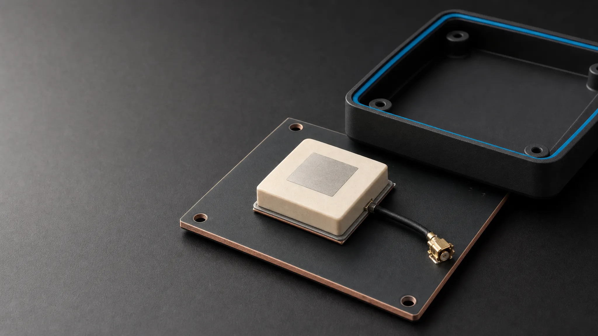
Do not classify an unfamiliar assembly from a photograph. A ceramic element and a ceramic-based assembly can differ in their electronics. Ask for the exact part number and RF configuration instead of assigning an LNA, bias voltage or accuracy class from its appearance.
Use real models to check architecture, not declare a winner
Two GNSource models illustrate why the distinction matters. The TDXL-BA800 active antenna specifications list an LNA gain of 38 ± 2 dB and a 3–12 V DC operating range. The TDXL-BA810 passive antenna specifications describe an external antenna for an appropriately designed RF chain, including engineering evaluation setups.
Both list a TNC-K interface, but that shared interface does not make them interchangeable. The active model introduces supply and gain requirements; the passive model requires an appropriate amplification architecture elsewhere. Review the exact receiver, signal requirements and installation before choosing either.
These are different design candidates, not the results of a controlled head-to-head test. Their specifications do not establish which will deliver the better position in your equipment.
Validate a candidate in the final device
An antenna that meets the paper requirements still needs an installed-system evaluation. Agree the acceptance criteria before ordering evaluation samples, especially if the project depends on repeatable survey or RTK performance.
Keep the receiver, firmware, configuration, required signals, cable assembly and power arrangement documented. When comparing candidates, use comparable mounting and sky conditions, and record any changes the different architectures require. Otherwise, a result attributed to the antenna may actually come from a changed cable, bias setting or receiver configuration.
Useful evidence can include acquisition behavior, tracking continuity, per-signal carrier-to-noise-density readings (C/N₀), receiver antenna-status indications and the project’s actual positioning results. Define which observations matter for the application and how long to collect them. A single successful fix or one strong C/N₀ reading is not an acceptance test for the entire system.
For RTK, include the receiver and correction-service configuration and the required solution behavior in the evaluation. Neither active nor passive labeling substitutes for that test.
Use the evidence in a GNSS antenna test report to separate component measurements from installed-system acceptance results.
Frequently asked questions
Does an active GPS antenna transmit to satellites?
No. In this receive-antenna context, “active” refers to powered amplification of the received signal. It does not mean that the antenna contacts satellites, requests corrections or transmits a navigation signal.
Can I connect a passive antenna to a receiver that supplies antenna bias?
Only with a documented compatible arrangement. Check whether bias can be disabled, the passive antenna’s permitted DC conditions, and whether the design requires a DC block. Also verify that the receiver’s RF front end supports the proposed passive path. Connector fit alone is not sufficient.
What is the maximum cable length for a passive GPS antenna?
There is no universal length that applies to every passive design. Evaluate the cable and connection losses at the required frequencies, the location and characteristics of the first LNA, and the receiver’s requirements. Use receiver-specific reference designs where available, then validate the installed configuration.
Does higher GPS antenna LNA gain improve RTK accuracy?
Not by itself. LNA gain helps set the signal level delivered through the RF chain, but must stay within the receiver’s allowed range. Antenna characteristics, noise, interference, required signals, mounting, receiver processing and corrections still affect the result. Compare the complete system against the project’s acceptance criteria rather than ranking antennas by gain alone.
Prepare a receiver-first antenna brief
Before requesting a recommendation or quotation, collect these inputs:
| Input | What to provide |
|---|---|
| Receiver | Manufacturer, exact model, hardware revision and relevant firmware/configuration |
| Required signals | The actual GPS/GNSS signals and any additional service frequencies |
| Power arrangement | Bias source, voltage, current capacity and DC pass/block requirements |
| RF input requirements | Allowed external gain and the documentation’s reference definition |
| Feedline | Cable type, length, connectors, adapters and inline equipment |
| Installation | External mounting or internal space, orientation, ground plane and enclosure |
| Evaluation | Application, acceptance criteria, sample quantity and expected production quantity |
Use the GNSource selector to prepare a receiver-specific antenna brief and request an antenna and RF-chain review together. If the receiver’s bias or input-gain limits are still unknown, obtain those requirements before selecting a candidate.