Choose GNSS antennas for deformation monitoring by defining the point being measured, documenting the mount, matching the receiver and RF path, and agreeing on the evidence needed to approve a sample. Keep that configuration identifiable through installation, maintenance and replacement.
The purchase should produce an antenna assembly your team can evaluate and reorder: the specified model, cable, interfaces, mounting arrangement and applicable documentation. This guide helps prepare that purchase. The project’s measurement team defines the monitoring method, acceptance criteria and interpretation of movement.
1. Define each point before choosing GNSS antennas for deformation monitoring
Start with the point plan and ask what each antenna is supposed to follow.
At a monitored point, the installation should represent the movement of the selected part of the structure or ground. The mount needs to transfer that movement without introducing uncontrolled movement of its own. At a local reference point, the measurement team has a different task: establishing and checking the reference against which observations are interpreted.
Those roles affect the mounting brief. A stable reference-station design cannot simply be copied to a point whose movement is the object of the measurement.
Natural Resources Canada’s reference-station installation guidance, dated September 2017, distinguishes the monument, mount, reference mark and antenna reference point, or ARP. Its stability recommendations concern reference stations. For a monitoring purchase, use those distinctions to describe the physical relationship that your project requires.
Create a short record for each point: identifier, monitored element or reference role, proposed mount, ARP location and how its relationship to the point will be measured. Include the reference source used by the processing team, whether local or external.
An installation drawing should make these relationships visible. It gives the antenna supplier a defined interface and gives the site team something more precise than “fit a survey antenna here.”
2. Document the mount and the reception environment
Take site photographs and add them to the drawing. Show the antenna location, nearby surfaces, sky obstructions, cable route and access needed for installation or replacement.
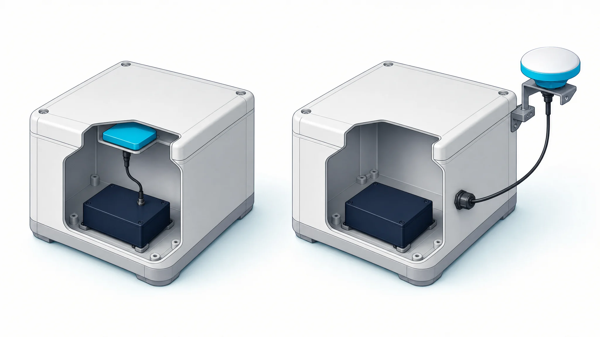
For the mechanical interface, record the mounting thread or bolt pattern, adapter stack, orientation mark and the method for locating the ARP. Ask the project engineer to specify the support and its mechanical requirements. The antenna drawing should identify the mating interface and any installation constraints. Use the measurement antenna catalog to compare candidate formats and interfaces.
Nearby walls, metalwork and other reflecting surfaces can introduce multipath, where reflected signals arrive along additional paths. Nearby transmitters and electronics can also affect reception. Record these conditions so that sample evaluation represents the intended site.
A useful installation record answers practical questions:
- Where does the cable attach, and how will strain be kept off the connector?
- Which orientation must be maintained, and how will it be checked?
- Will a radome or other protective cover be part of the installed assembly?
- What environmental exposure must the antenna, connections and support withstand?
Specify the assembled installation, including connector sealing and cable support. A protection rating for an antenna enclosure addresses that enclosure; the completed cable connection and mounting arrangement need their own review.
By the end of this step, the sample installation should be reproducible from the record. That makes subsequent comparisons and replacement checks easier to interpret.
3. Check the receiver, signals and complete RF path
Use the exact receiver model and its input requirements to screen candidates. List the GNSS signals the project will use, including the required GPS bands and other constellations’ signals. Confirm their coverage in the antenna specification.
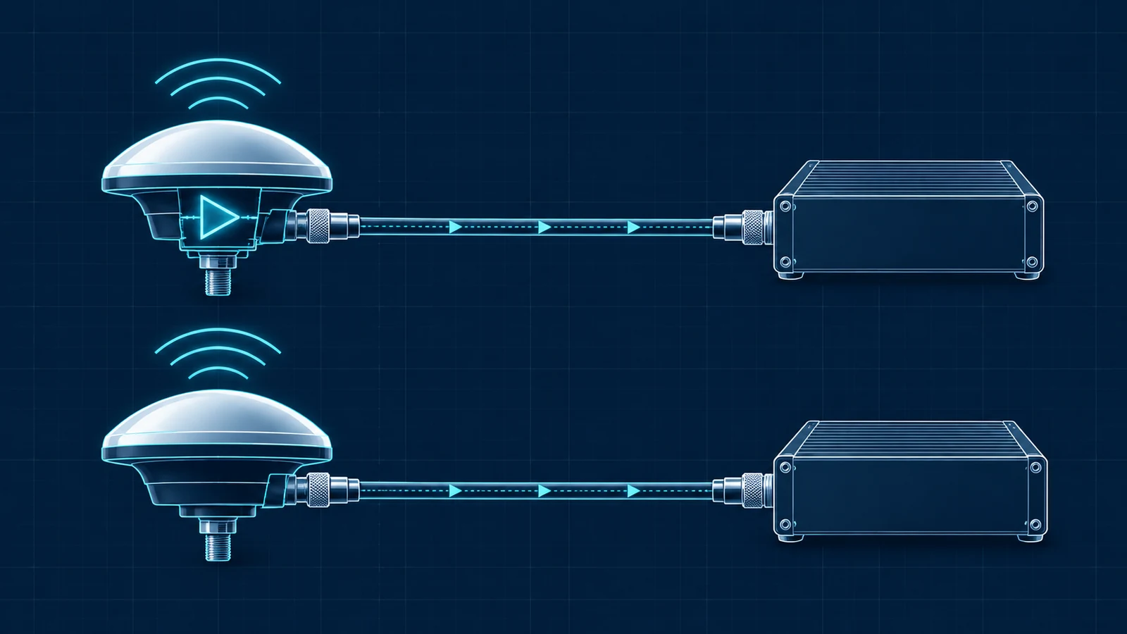
Then document the complete radiofrequency path: antenna, cable assembly, adapters, protection devices and receiver input. For an active antenna, check the available bias voltage and current capacity against the antenna’s requirements. Identify whether intermediate components pass the required DC supply.
Keep element gain and low-noise amplifier, or LNA, gain separate. The former describes directional reception; the latter describes electronic amplification. Ask where each figure is defined and assess cable losses against the receiver’s permitted input conditions.
NovAtel’s coaxial cable selection guidance connects cable impedance, loss and connector selection to receiver operation. Its numerical limits apply to the documented OEM7 equipment. For your installation, use the limits of the selected receiver and the loss of the actual cable assembly.
For example, TDXL-BA802 is an external active antenna with GPS L1/L2/L5 among its listed signals, a TNC-K connector, a 3–16 V DC operating range and a 5/8-11 mounting interface. Those fields provide specific inputs for a compatibility review. The review must still include the receiver, mating parts, cable and site requirements.
The active and passive antenna RF-chain guide provides a separate checklist for power and amplifier placement. The output is a named RF configuration that can be quoted and tested without leaving the cable or power arrangement to assumption.
4. Match calibration to the installed antenna and radome
Ask the processing lead which antenna calibration information the project requires before approving a model.
The mechanical ARP identifies a physical reference. The electrical phase center can have an offset relative to it, described by phase center offset, PCO, and direction-dependent behavior described by phase center variation, PCV. Request the applicable definitions, signals and measurement conditions when reviewing these data.
The NGS antenna calibration service identifies calibrations by antenna code and radome code and provides files in formats including ANTEX. That identity matters when selecting data for an installed combination.
Where calibration files are required, record the antenna designation, radome designation, file source, version and processing-software requirements. Have the processing team match ANTEX records to the antenna configuration and check the signals and reference frame it uses. Include the ARP drawing and orientation instructions in the same package.
A catalog phase-center figure describes a specified antenna property. An applicable calibration file supplies information for a particular processing workflow. Check each requirement separately when comparing offers.
For a private monitoring project, the required evidence follows its measurement specification. For a project with network requirements, identify the network’s exact conditions. The buyer should know which documents must accompany the sample and which must match the delivered production configuration.
5. Agree on sample acceptance before the trial
Set the trial conditions and acceptance criteria with the measurement team before collecting data. Record the antenna identity, receiver and firmware, tracked signals, cable, mount, orientation, processing settings and reference source.
Original Université Gustave Eiffel research on GNSS structural monitoring evaluated antenna–receiver combinations and processing parameters in static and dynamic experiments. That is a useful reminder to evaluate the assembled measurement configuration. The study’s results belong to its experimental conditions.
Separate the evidence your trial will produce:
| Record | Question it helps answer | Context to retain |
|---|---|---|
| Position estimates and comparison with the project’s chosen reference | Does the tested configuration meet the agreed measurement requirement? | Coordinate frame, horizontal and vertical components, observation windows, comparison method and uncertainty. |
| Observation-quality indicators | How did reception behave during the trial? | Signals, satellites, elevation, C/N0 where available, interruptions and nearby equipment states. |
| Data and solution availability | Were the required observations and outputs available when needed? | Receiver logs, processing intervals, communications gaps and corrections used, where applicable. |
| Installation and intervention record | Which physical configuration produced the data? | Antenna and radome identity, cable, mount, orientation, photographs and event times. |
C/N0, carrier-to-noise-density ratio, is a reception indicator. An RTK fixed-state indication describes a solution state. The trial needs the agreed comparison evidence to establish position performance, together with the records needed to interpret it.
Use our guide to reviewing GNSS antenna test reports to separate component evidence from system results. Choose the trial duration and operating scenarios around the project requirement. A short open-sky demonstration may leave questions about the actual installation unanswered. Define what must be observed at the intended site, what supporting measurements are needed and who reviews the result.
If comparing candidates, document the differences between trials. Changing the antenna, cable, location and processing together makes it difficult to attribute a change in the results. Approve a clearly identified configuration and retain its underlying records.
6. Put configuration and replacement requirements in the RFQ
Turn the previous steps into a request for quotation that a supplier can answer precisely. Keep commercial quantities alongside the technical package, so the sample and subsequent production order refer to the same configuration.
| RFQ item | Information to send or request |
|---|---|
| Point and application | Monitored or reference role, installation drawing and environmental conditions. |
| Receiver and signals | Exact receiver variant, required signals, antenna-input requirements and bias supply. |
| Cable and interfaces | Cable type and length, connector details, adapters, intermediate components and mounting interface. |
| Antenna documentation | Model and revision, drawings, electrical specifications and applicable calibration requirements. |
| Sample approval | Agreed configuration, evidence to collect, acceptance criteria and review responsibilities. |
| Supply and replacement | Sample quantity, production forecast, required identification and notification of proposed changes. |
Include replacement planning before the first production order. Specify which parts define the approved configuration and how a proposed successor, different radome or alternative cable assembly will be reviewed.
The IGS CORS guidelines, version 1.1 of April 2026, discuss antenna–radome identity, equipment metadata and changes in computed position following antenna replacement, even when the ARP is restored. These requirements concern IGS stations; the continuity issue is also a reason to plan change records for a monitoring project.
For each intervention, preserve the time, affected point, before-and-after configuration, mounting changes and applicable processing records. Ask the measurement team to decide what must be checked again. Keep that decision with the installation history rather than treating a replacement as equivalent solely because it fits the same thread.
Frequently asked questions
Does a ±2 mm antenna specification mean 2 mm displacement accuracy?
Read the definition and conditions attached to that specification. A phase-center value describes antenna behavior; displacement performance concerns the measurement configuration, site, reference and processing. Establish the latter through the project’s agreed evaluation.
Does every monitoring point need a choke-ring antenna?
Select against the installation and measurement requirements. Compare the candidate’s documented reception characteristics, calibration applicability, size, mass and mounting needs. Where a network prescribes antenna requirements, include them in the selection brief.
Should calibration availability be checked before ordering samples?
Yes, when the processing workflow requires it. Identify the antenna–radome combination and the applicable data before purchase, so the sample trial can use the intended configuration and processing inputs.
Is higher LNA gain the main selection criterion?
Assess it within the receiver’s input requirements and complete RF path. Cable loss, filtering, power and element behavior all matter. Comparing the largest amplification number alone leaves those requirements unresolved.
For a GNSource project review, send the point roles, receiver model, signal list, cable and mounting drawing, calibration requirements and sample quantity. These inputs allow the team to identify candidates and review adaptations to existing antenna platforms for your application.