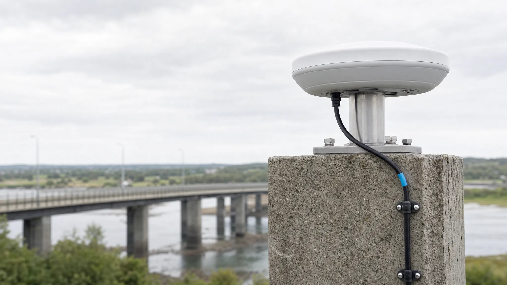
Choose a GPS patch antenna ground plane using the selected antenna’s reference design, then evaluate it in the finished assembly. Its dimensions, shape and position relative to the patch affect the result. A larger conductive area or a good impedance match alone does not establish better positioning performance.
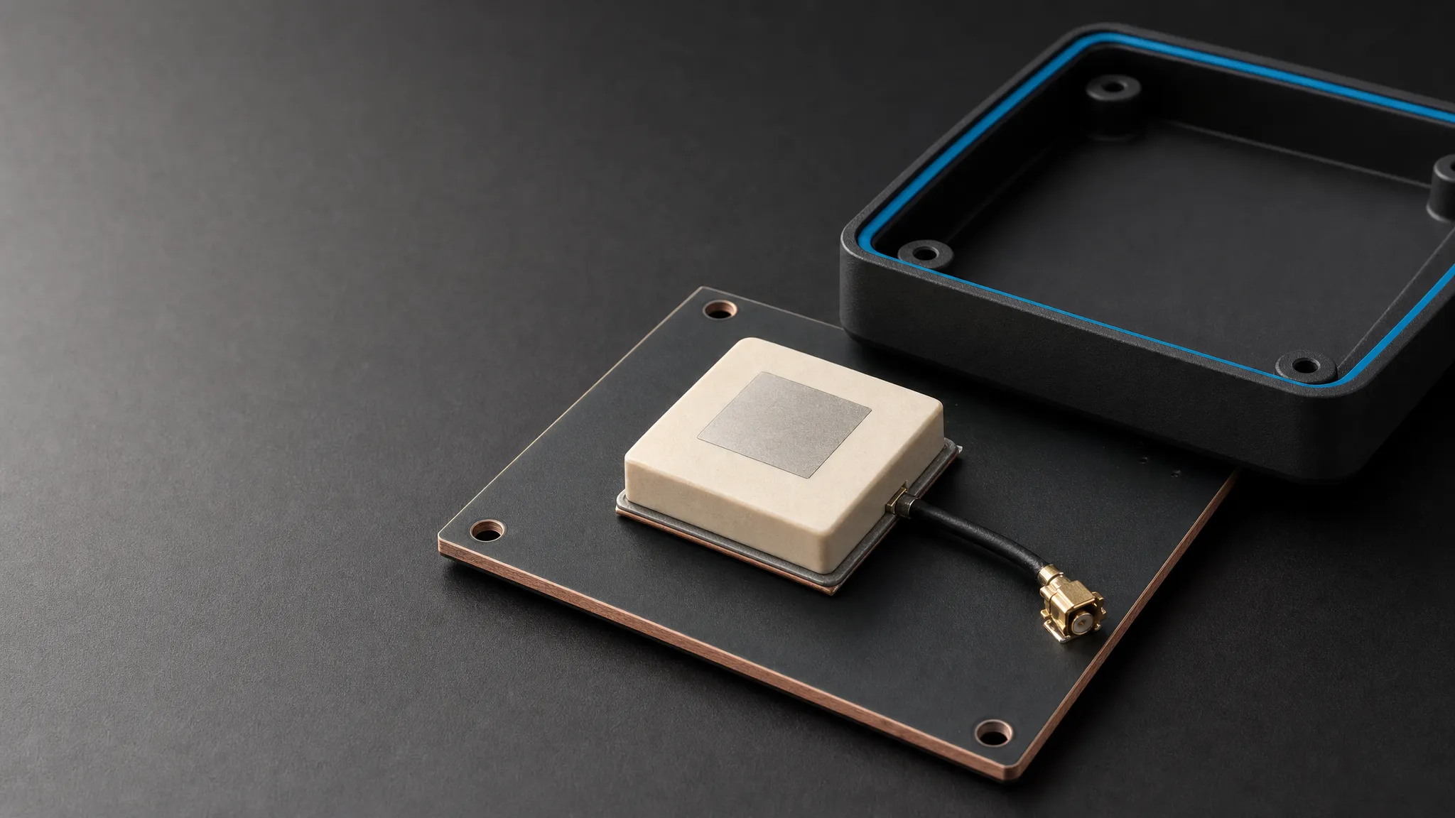
For a device OEM, the ceramic block is one part of the installation. The PCB, housing, nearby electronics and feed connection also need space and verification before the design is frozen.
These steps cover a ceramic patch integrated onto a board or supplied as an internal assembly. For a magnetic antenna mounted on a vehicle roof, follow the instructions for that antenna and mounting arrangement.
1. Identify the assembly before reserving PCB space
Start with the exact part number, revision and intended delivery configuration. Establish whether you are integrating a bare patch, an antenna on its own board, or an assembly that already includes electronics and a cable. These options create different mounting and receiver-interface tasks.
Ask for the mechanical drawing and reference installation associated with that configuration. Record the antenna body, supporting board, total installed height, feed arrangement and mounting method separately. A small ceramic footprint does not describe the complete volume needed for connections and assembly.
Confirm the signals required by the receiver before comparing candidates. For example, GNSource’s WL-GPSI12122 specifies 1575.42 MHz, while WL-GPSI25254-100 specifies 1561.098 MHz and 1575.42 MHz. Compare the ceramic patch models for device integration against the project’s required signals and operating bandwidth for the actual assembly.
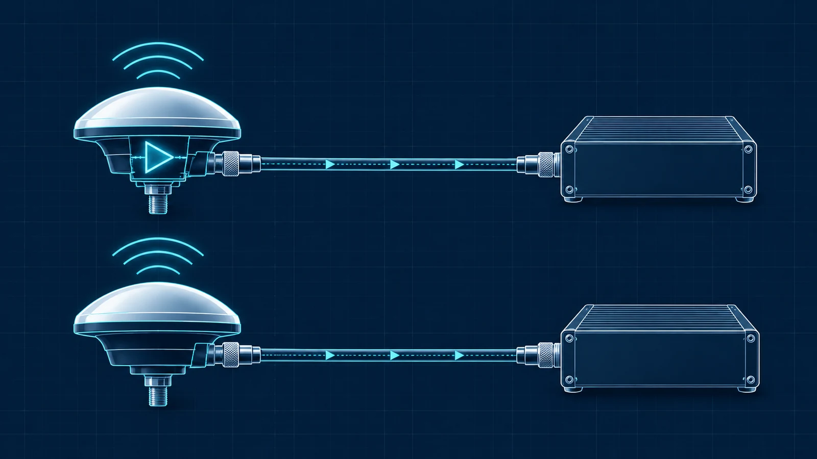
If the receiver requires additional GNSS bands, put them in the sample request. Also confirm the antenna’s active or passive architecture and any supply requirements. Ceramic construction alone does not identify an LNA or establish compatibility with a particular receiver.
The output of this step is a part-and-interface record tied to a real sample configuration.
2. Reproduce the specified GPS patch antenna ground plane
Locate the ground plane in the antenna manufacturer’s reference design. Identify which conductive surface it uses, its shape and dimensions, and where the antenna sits relative to its edges. Then compare that arrangement with your proposed board.
A GNSS antenna ground plane cannot be judged by area alone. The u-blox GNSS Antennas application note, R03 (2019) explains how patch placement and ground-plane geometry affect gain, radiation pattern, impedance matching and axial ratio, a measure of polarization quality. Its worked example shows why increasing size does not improve every property together.
For a concrete reference, the Taoglas SGGP.12.4.A.02 datasheet, revision D, specifies that part at the center of a 50 × 50 mm ground plane and gives its associated footprint requirements. That dimension belongs to the SGGP reference installation; choose the arrangement specified for your own antenna.
| Record | Compare the reference with the proposed assembly |
|---|---|
| Conductive surface | Which PCB layer, antenna board or separate surface forms the specified plane? |
| Outline | Do length, width, shape, slots and cutouts match the reference conditions? |
| Antenna position | Is it centered or offset, and how close is it to each edge? |
| Footprint and feed | Are pads, feed points, ground connections and clearances correct for the exact part? |
| Surroundings | What components or structural metal occupy the nearby region? |
Mark the differences on the layout drawing. If mechanical constraints require an irregular board or an off-center patch, request a review of that configuration before treating the reference performance as applicable. Simply adding copper elsewhere does not recreate the original installation.
3. Review the closed housing and nearby components
Use a representative mechanical assembly when assessing the layout. Include the cover, battery, display, shields, fasteners and mounting supports that will surround the antenna in service.
Nearby materials can change the antenna’s electrical behavior even when they do not touch the ceramic. A plastic cover can alter its environment; conductive parts can change the receiving path or pattern. Identify the intended antenna orientation and the direction in which the device normally faces the sky.
Keep the model-specific clearances on the drawing, including space for manufacturing tolerances and assembly access. A general instruction to “keep metal away” is too vague to review: show the actual bracket, shield or battery and its position.
If the closed enclosure behaves differently from the open prototype, preserve both configurations for comparison. Avoid moving the antenna, adding a different cable and changing the cover simultaneously. That would make it difficult to identify which change affected reception.
The mechanical record should show the materials, parts and positions that will be represented in the next sample build.
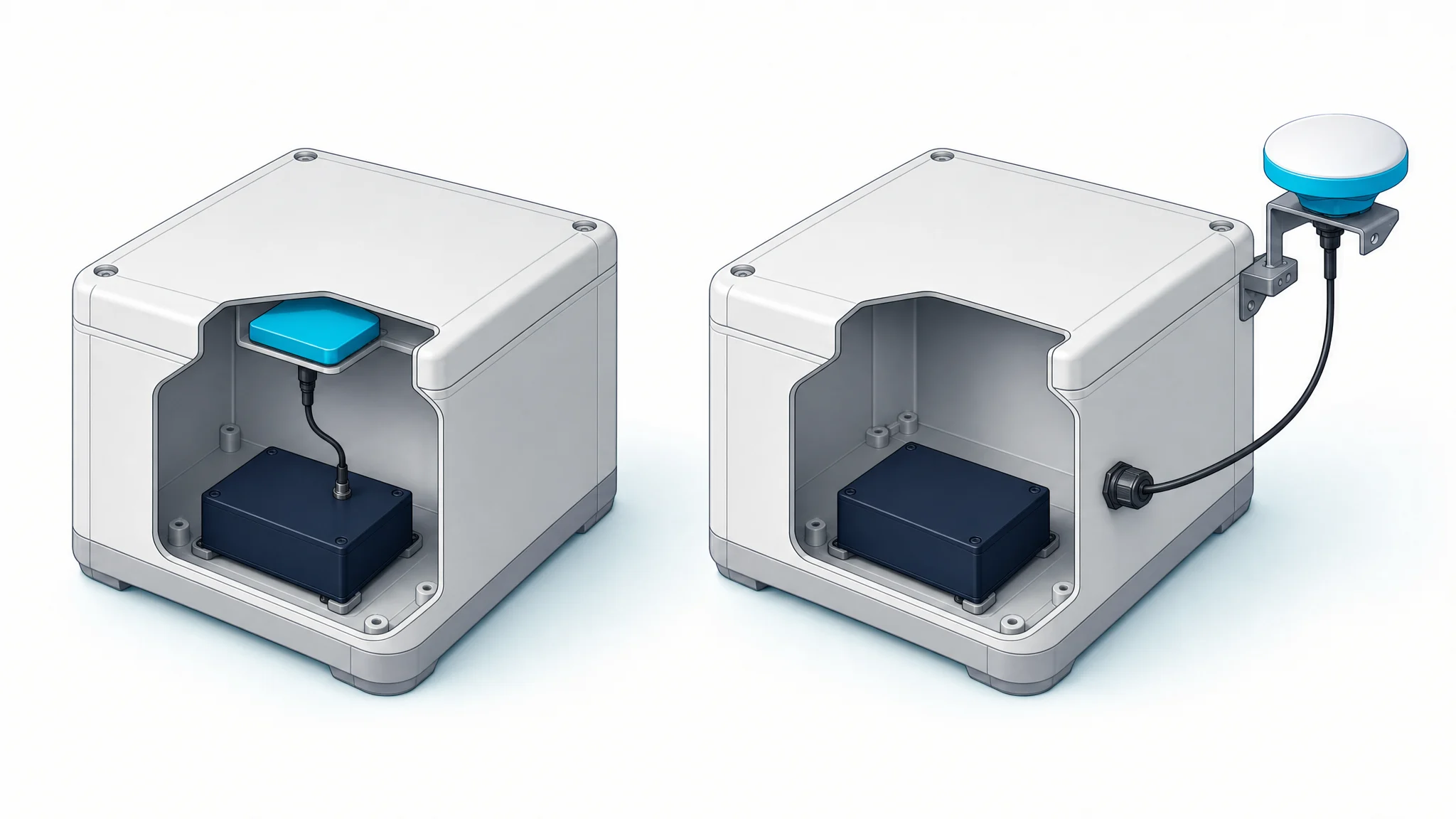
If the closed housing leaves no suitable internal position, compare embedded and external installation options before committing to a board layout.
4. Fix the RF feed and cable route
In the GPS antenna PCB layout, distinguish the antenna’s specified ground-plane arrangement from the feed connection and its return path. Follow the selected part’s footprint and the receiver’s RF-interface requirements for both.
For a board feed, document the PCB stack-up, transmission-line geometry, connectors and any matching or protection components. Calculate the trace geometry for that stack-up and intended impedance rather than copying a trace width from an unrelated board.
For a cable-fed assembly, record the cable type, length, mating connector, exit direction and installed route. Provide strain relief and the bend allowance required by the cable assembly. Check that closing the housing will not pull on the connector or push the cable into a different position.
Review the complete RF chain for losses, supported frequencies and receiver input requirements. For an active antenna, include its power path. Keep noisy electronics and transmitting radios in the installation review, and document their operating states for testing.
Once a sample arrangement is chosen, hold its routing consistently across builds. Otherwise, a ground-plane comparison may also become a cable-placement comparison.
Use the receiver requirements to check antenna bias and amplifier placement alongside the feed and cable arrangement.
5. Separate antenna measurements from receiver results
A layout review needs evidence that answers the question being asked. Impedance measurements, radiation measurements and a receiver position log describe different parts of the system.
The Taoglas GPS Patch Integration application note, APN-12-8-002.B (2012) discusses housing effects and explains why in-device radiation-pattern and gain measurements matter alongside impedance matching. A matching result cannot, by itself, describe how well the installed antenna receives signals from different directions.
Choose the evidence needed for your project and state its measurement configuration:
| Evidence | What it helps establish | What still needs evaluation |
|---|---|---|
| S11, return loss or VSWR | Impedance behavior across the required frequencies at the defined measurement point | Installed radiation behavior and complete receiver performance |
| Radiation pattern, gain and polarization data | Receiving characteristics in specified directions and configurations | Operation with the host electronics and positioning workflow |
| Receiver diagnostics, including C/N0 and TTFF | Reception and acquisition behavior under recorded conditions | Position error against an appropriate reference |
| Positioning observations | Whether the assembled system meets its agreed application criteria | Repeatability across the other required conditions and sample builds |
Define the measurement point, fixture and assembly state when recording RF results. If the antenna includes powered electronics, use a test setup appropriate to that assembly rather than applying a bare-element measurement method without review.
For receiver tests, record carrier-to-noise density (C/N0), signals tracked and time to first fix (TTFF) where relevant. Define the startup conditions so acquisition results are comparable.
For an RTK project, also record the correction source, correction availability, solution status and position result. A fixed solution or a higher C/N0 reading alone does not establish that the ground-plane change improved accuracy. Differences in sky view or multipath can also affect the comparison.
Our guide to interpreting RF and receiver test evidence explains how to separate those questions when reviewing a supplier report.
6. Compare changes against a documented baseline
Begin with a reference configuration and a proposed installed configuration. Give each a clear identity: antenna sample, board revision, ground-plane outline, mounting position, housing parts and cable route.
Use the same receiver hardware, firmware, signal settings and logging procedure where practicable. Keep observing conditions comparable and record differences you cannot control. Set acceptance criteria from the application requirements before interpreting results.
Organize the comparison around the change being investigated:
- Ground-plane or board change: keep the antenna, feed arrangement and other assembly details consistent; document the altered geometry.
- Cover or nearby-part change: preserve the antenna position and cable route while checking the representative mechanical configuration.
- Cable-route change: hold the antenna and housing arrangement constant and record the route being evaluated.
- Electronics activity: compare the defined processor, display, radio or charging states using the same physical assembly.
After isolating important differences, evaluate the complete intended combination. Passing separate checks on individual parts does not establish that their final arrangement meets the project criteria.
Keep before-and-after records with the drawings and logs. If results do not meet the agreed criteria, use those records to decide whether to revise placement, request a supplier tuning review or evaluate another antenna. The appropriate response depends on the observed problem; adding a larger plate is only one possible design change.
Frequently asked questions
How large should a GPS patch antenna ground plane be?
Start with the exact antenna’s specified reference installation. Include the plane’s shape, antenna position and surrounding assembly, then evaluate any differences in your design. A dimension quoted for another patch is a reference for that configuration, not a universal minimum.
Is a larger GPS antenna ground plane always better?
No. Changing size can affect tuning, gain, radiation pattern and polarization together. Compare the properties required by the application rather than assuming that the largest conductive surface gives the best installed result.
Does good VSWR mean the device will achieve its positioning target?
No. VSWR describes impedance matching at a defined point. Positioning also depends on the installed receiving behavior, receiver, environment, processing and any corrections. Use the appropriate antenna and system evidence alongside the matching measurement.
Can the PCB be shortened after the prototype passes?
Treat a changed ground-plane outline, antenna position or nearby layout as a design revision. Review which evidence remains applicable and repeat the relevant checks on the revised assembly before accepting it for production.
Send the integration inputs with the sample request
Prepare a compact package that engineering and procurement can use together:
- The antenna part number, sample configuration and required GNSS signals.
- The receiver model and its antenna-interface requirements.
- The PCB outline, relevant layers and an annotated comparison with the reference ground plane.
- The enclosure drawing, materials, nearby components and operating orientation.
- The feed or cable details, connector arrangement and installed routing.
- The planned evaluation criteria, available test evidence, sample quantity and expected production volume.
For a GNSource platform configuration and integration review, start with the receiver, required signals and annotated board-and-enclosure drawings. These inputs help define suitable samples and the layout questions to resolve before the mechanical design is frozen.