The embedded vs external GNSS antenna decision starts with the installed receiving position. Choose an embedded antenna when the finished device can provide that position, enough installation space and a compatible RF connection. Consider an external antenna when separate mounting gives you better control over sky view or separation from the device’s electronics.
For an OEM, this decision affects the enclosure, PCB layout, cable routing, assembly and field installation. It is worth resolving before those parts of the design become difficult to change.
The practical goal is to select an architecture that can be built consistently and evaluated in the conditions where the device will operate.
Embedded vs external GNSS antennas: the quick comparison
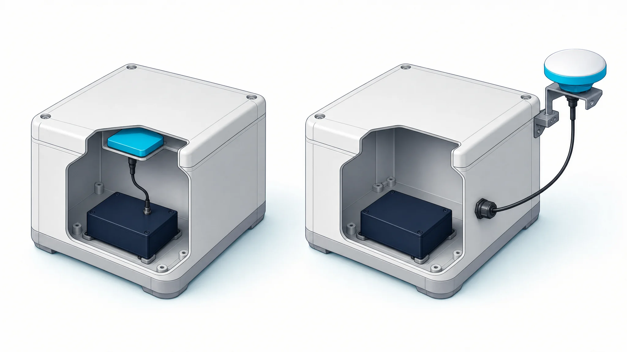
Here, embedded means an antenna installed inside the finished device’s main enclosure. External means a separate antenna assembly mounted outside that enclosure, usually connected by a cable. Define this boundary in your project brief: an antenna described as “external” to a receiver module may still sit inside the finished device.
| Decision | Embedded antenna | External antenna |
|---|---|---|
| Receiving position | Constrained by the device’s shape, contents and orientation | Can use a separate position, subject to mounting and cable constraints |
| Space to reserve | Antenna, required ground plane, clearances, support and feed connection | Mounting surface, antenna body, cable entry and connector clearance |
| RF environment | Evaluated with the host enclosure, PCB and nearby electronics | Evaluated with its mounting surface, surroundings and complete cable path |
| Assembly work | Internal mounting and routing become part of device production | Cable installation, external mounting and any enclosure penetrations need planning |
| Environmental protection | Depends on the finished enclosure and assembly | Depends on the antenna assembly, connectors, cable entry and installation |
| Service access | May require opening or replacing the device | May allow separate replacement if the installation remains accessible |
| Active or passive | Either architecture is possible | Either architecture is possible |
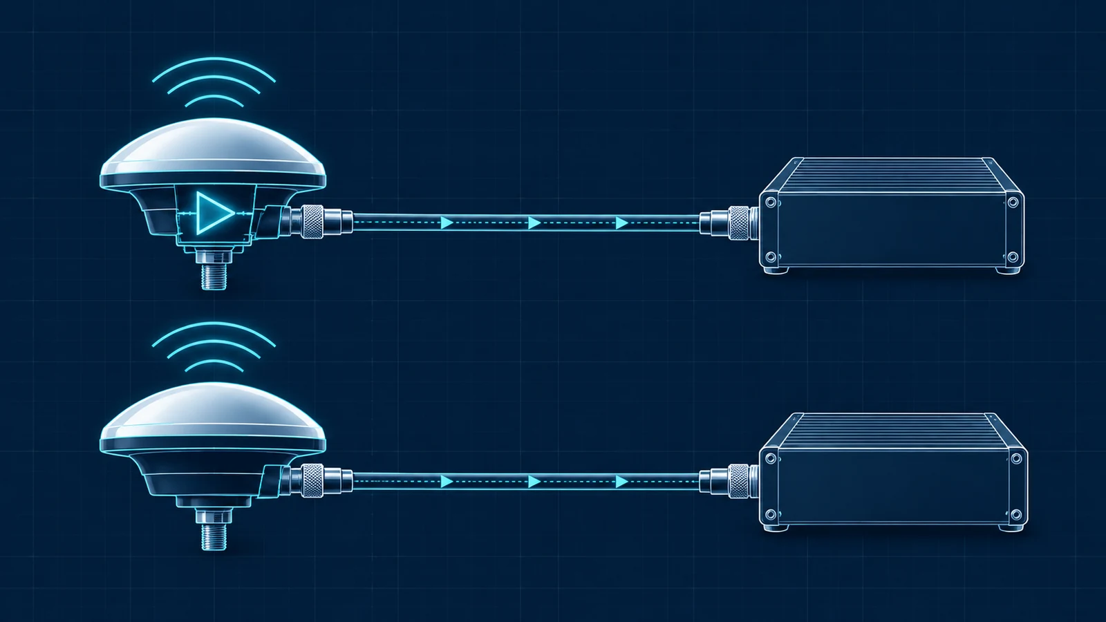
The last row matters. “Embedded” describes placement; “active” describes an assembly with a powered amplifier. Keep these questions separate when comparing quotations.
Reserve the whole installed volume
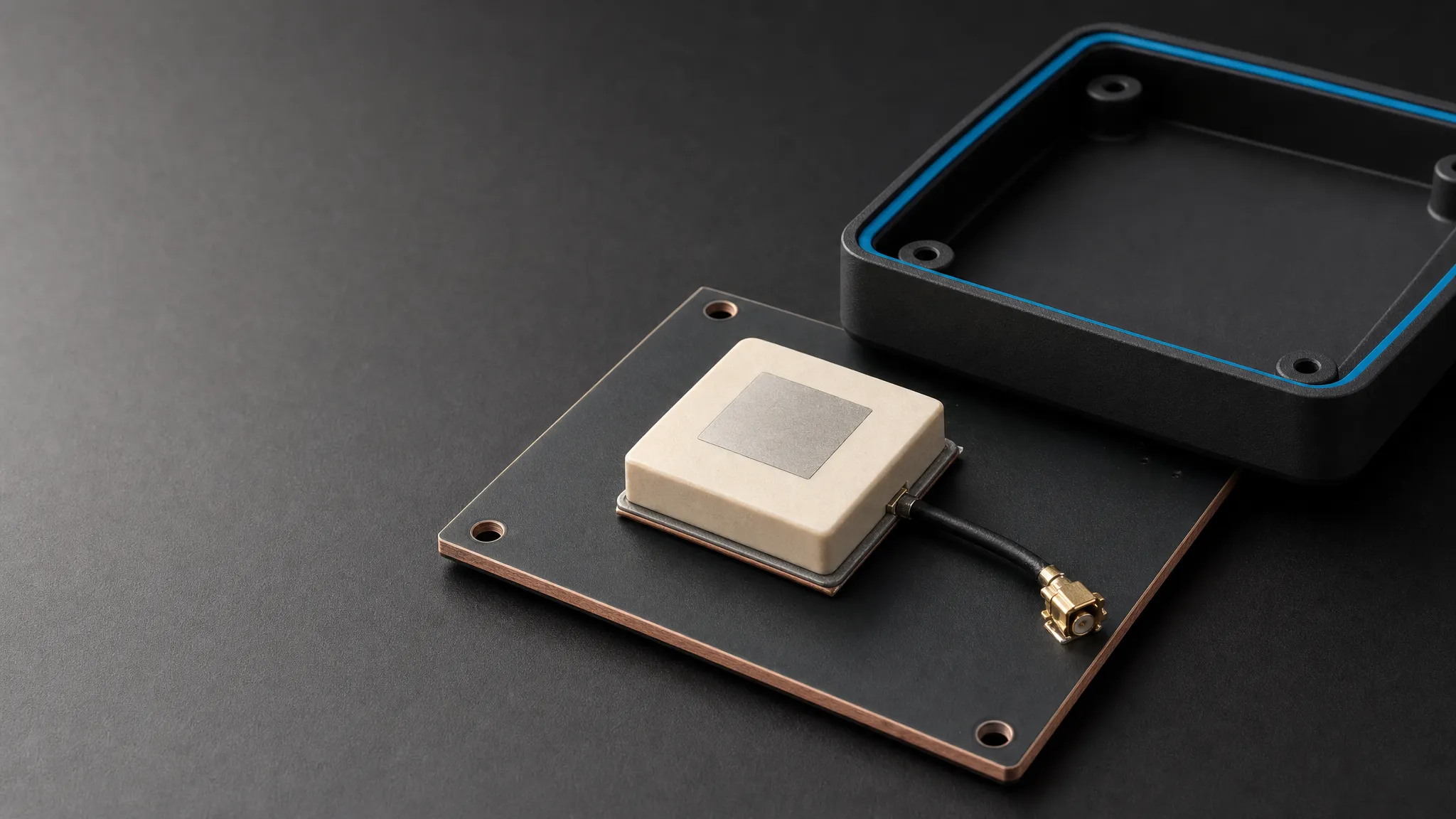
An antenna’s body dimensions are only the starting point for a mechanical review. Embedded GNSS antenna integration also needs room for the mounting arrangement, any specified ground plane or keep-out area, connector engagement and cable routing.
For example, GNSource’s TDXL-BA730 embedded model is an active antenna with an MCX interface and an antenna body measuring 59 × 63 × 17 mm. The TDXL-BA720 is an active external antenna with a TNC-K interface. Both include GPS L1/L2 in their published signal lists, yet their installation tasks differ. The embedded model needs a suitable position within the device; the external model needs a mounting location and cable route outside it.
This example illustrates the space and connection questions to resolve before evaluating positioning performance. The BA730’s body dimensions do not include every clearance needed to mate its connector or route a cable.
Before freezing the enclosure, place the proposed antenna and its connection in the assembly drawing. Check the cable bend, strain relief, fasteners and assembly access. An antenna that fits in CAD may still leave no practical way to connect or replace it.
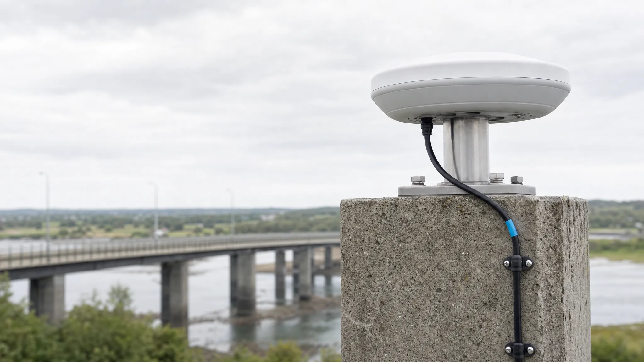
For an external arrangement, review the complete route from the antenna to the receiver. Include mounting hardware, cable entry, connector access and protection from cable pull or repeated movement.
Check the closed enclosure, not just the open prototype
A working antenna on an open development bench does not establish how the closed device will receive satellite signals. Housing materials, nearby conductors and the final orientation can change the antenna’s operating environment.
Plastic is not automatically irrelevant to RF performance. In its product-specific M1575HCT-22-P integration and tuning guidance, Maxtena describes the effects of cover material and geometry, and recommends including the PCB, plastic and nearby metal in prototype evaluation. Its mounting dimensions apply to that product; the broader lesson is to evaluate the actual assembly.
Ground-plane requirements are also antenna-specific. The u-blox GNSS Antennas application note, revision R03 (2019) explains how ground-plane size and shape affect patch antennas. It does not establish a universal ground-plane dimension for other antenna designs.
For a ceramic patch layout, use the ground-plane and enclosure integration checklist to document the reference geometry and changes to evaluate in samples.
Review the enclosure in its operating configuration:
- Is the receiving face suitably oriented when the device is carried, installed or moving?
- Do a battery, display, shield, bracket or conductive coating occupy the proposed receiving area?
- Can the antenna be separated from noisy electronics within the available space?
- Will the user, mounting structure or platform obstruct the intended sky view?
An external antenna offers another placement option when internal constraints are difficult to resolve. It still needs a suitable location: a remote antenna underneath an obstruction has not solved the receiving-position problem.
Define the receiver connection before comparing samples
After choosing a possible location, check the complete antenna-to-receiver connection. Physical placement does not determine electrical compatibility.
Record the required GNSS signals and confirm that both antenna and receiver support them. A generic “GNSS” label does not establish support for every band, and a single frequency point does not establish a continuous operating bandwidth.
Then identify whether the proposed antenna assembly is active or passive. For an active antenna, check its supply requirements against the receiver’s bias arrangement and the actual DC path. For either architecture, account for the cable, adapters and other components when checking the receiver’s RF-input requirements.
A short internal feed and a longer external cable create different RF-chain questions. The active and passive antenna compatibility checks explain how receiver bias and amplifier placement enter this decision. Do not select an amplifier gain or maximum cable length from the embedded/external label alone.
Finally, specify the connector’s mating arrangement, mounting geometry and cable assembly. A connector family name on two documents is not enough to confirm that the finished parts will connect as intended.
Define what “high precision” must mean for this device
For a survey receiver, reference installation or monitoring instrument, ask what the system must demonstrate under its intended operating conditions. Multi-band reception, carrier-phase observations and stable mounting can matter, but a list of supported signals is not a complete positioning-performance specification.
Where processing requires antenna phase-center corrections, identify the calibration data for the exact antenna configuration. The NOAA National Geodetic Survey antenna calibration service identifies calibrations using antenna and radome codes. A file for a different assembly should not be treated as interchangeable because the products look similar.
Include the required calibration evidence in the sample request if it is part of the project, and confirm availability for each candidate assembly.
Set the acceptance criteria before testing. A project may need a specified position error, reliable RTK fixed-solution availability, repeatable startup behavior or stable operation across device orientations. Agree the conditions and reference method as well as the result being measured. You can narrow antenna candidates by project requirements before planning the sample evaluation.
Compare installation and lifetime costs
An embedded design can remove a separate external installation step, but it adds requirements to enclosure design, internal assembly and verification. A late change to the battery, housing or PCB may require another antenna evaluation.
An external design can keep the antenna assembly independently accessible. It also adds mounting hardware, cable management and potentially a sealed cable entry. Replacement is easier only when the installed antenna and connectors can actually be reached.
Ask procurement to compare the proposed assemblies on the same basis:
- Parts, cables, adapters and mounting hardware included in the quotation.
- Assembly and installation work required for each device.
- Sample evaluation and any mechanical changes still needed.
- Service access and replacement procedure.
- Which component or enclosure changes trigger re-evaluation.
There is no reliable rule that embedded is always cheaper or external is always easier to maintain. The answer depends on the product and its installation.
Compare candidates in their installed configurations
When both architectures are feasible, a controlled sample comparison is more useful than a decision based on appearance. Build each candidate into a representative assembly and document the differences.
Keep the receiver hardware, firmware, signal configuration and logging method consistent where possible. For RTK work, record the correction source and its availability. Use comparable observing conditions, and avoid attributing a change in surroundings or satellite visibility to the antenna alone.
| Evaluation | Configuration to record | What it helps you assess |
|---|---|---|
| Mechanical fit | Closed enclosure, supports, connector and routed cable | Whether the assembly can be built and serviced |
| Powered-device operation | Normal processor, display, radio and charging states | Whether reception changes with device activity |
| Orientation and surroundings | Representative device poses, mounting surfaces and obstructions | Whether the receiving position suits real use |
| Reception and startup | Signals tracked, carrier-to-noise density (C/N0), defined startup conditions and time to first fix (TTFF) | Reception and acquisition behavior under recorded conditions |
| Positioning | Suitable reference, processing settings, corrections and solution status | Whether the complete system meets the project’s acceptance criteria |
| Assembly repeatability | Sample identity, antenna position, cable route and enclosure revision | Whether results remain consistent across builds |
C/N0 and satellite counts help diagnose reception; they are not substitutes for a position-error measurement. Likewise, an RTK “fixed” status should be assessed alongside the position result and the conditions in which it was obtained. Use the guide to interpreting antenna test evidence to check which configuration and result a report actually covers.
For external samples, make the mounting repeatable. NovAtel’s OEM7 antenna mounting guidance calls for a clear view of the sky and a stable supporting structure. Record where the antenna sits and whether it moves relative to the device or platform.
Use this evaluation plan to produce a documented sample configuration and a decision against agreed acceptance criteria.
Frequently asked questions
Is an external GPS antenna always more accurate than an internal one?
No. An internal vs external GPS antenna comparison must account for the installed receiving position, antenna characteristics, receiver, processing and surroundings. External placement can help when it provides a more suitable location, but the label alone does not establish accuracy.
Can an embedded GNSS antenna be active?
Yes. An embedded assembly can contain a powered low-noise amplifier. Confirm the antenna’s power requirements and the receiver’s supported RF arrangement separately from its mounting location.
Can I put a GNSS antenna inside a metal enclosure?
Do not assume it will receive adequately through the enclosure. Review the proposed receiving path, openings or RF-transparent area, nearby metal and actual assembly. An external mounting position is another option to evaluate when the enclosure prevents suitable internal placement.
Does an external antenna’s IP rating protect the whole installation?
No. Check which assembly and conditions the rating covers. The host enclosure, connector mating, cable entry and mounting arrangement also need to meet the application’s environmental requirements.
Prepare an integration brief before ordering samples
An internal vs external GNSS antenna decision is easier to review when the RF, mechanical and procurement requirements are in one document. Send the following information with your sample request:
| Input | What to provide |
|---|---|
| Receiver and signals | Exact receiver model, hardware revision and required GNSS signals |
| Electrical interface | Supported antenna architecture, bias supply and RF-input requirements |
| Enclosure | Material, coatings, drawings, nearby electronics and normal operating orientation |
| Installation space | Available volume, mounting points and relevant PCB or ground-plane constraints |
| Connection | Connector details, cable type and length, routing and strain relief |
| Operating environment | Installation location, exposure, movement and service-access requirements |
| Evaluation and procurement | Acceptance criteria, required evidence, sample quantity and expected production volume |
If both arrangements remain possible, identify the open choices in the brief and request suitable evaluation candidates. This gives engineering and procurement a shared basis for comparing the complete assemblies.
For a GNSource OEM integration review, start with the receiver model, enclosure drawing and required signals. Those inputs help narrow the antenna options and define the sample configuration before committing the device to an embedded or external layout.