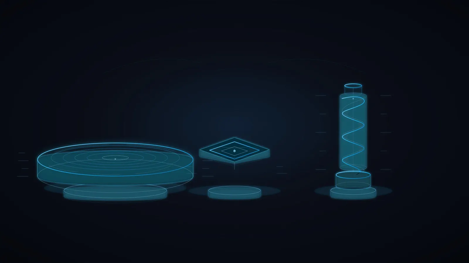
A choke ring vs patch antenna comparison cannot tell you positioning accuracy from shape alone. A choke ring is a structure used around a radiating element to control reception; patch and helical describe element designs. These categories can overlap, and each includes products with different bandwidths, patterns and calibration evidence.
For a fixed reference station, the decisive evidence may be an applicable calibration and a stable monument. For a mapping drone, it may be the installed pattern, mass and carrier tracking during turns. Start with those requirements before choosing a form factor.
Choke ring vs patch antenna: compare the actual assemblies
| Design | Why consider it? | What to check before selection |
|---|---|---|
| Choke ring assembly | Pattern control for fixed survey or reference installations | Supported bands, below-horizon response, mass, mounting and applicable calibration |
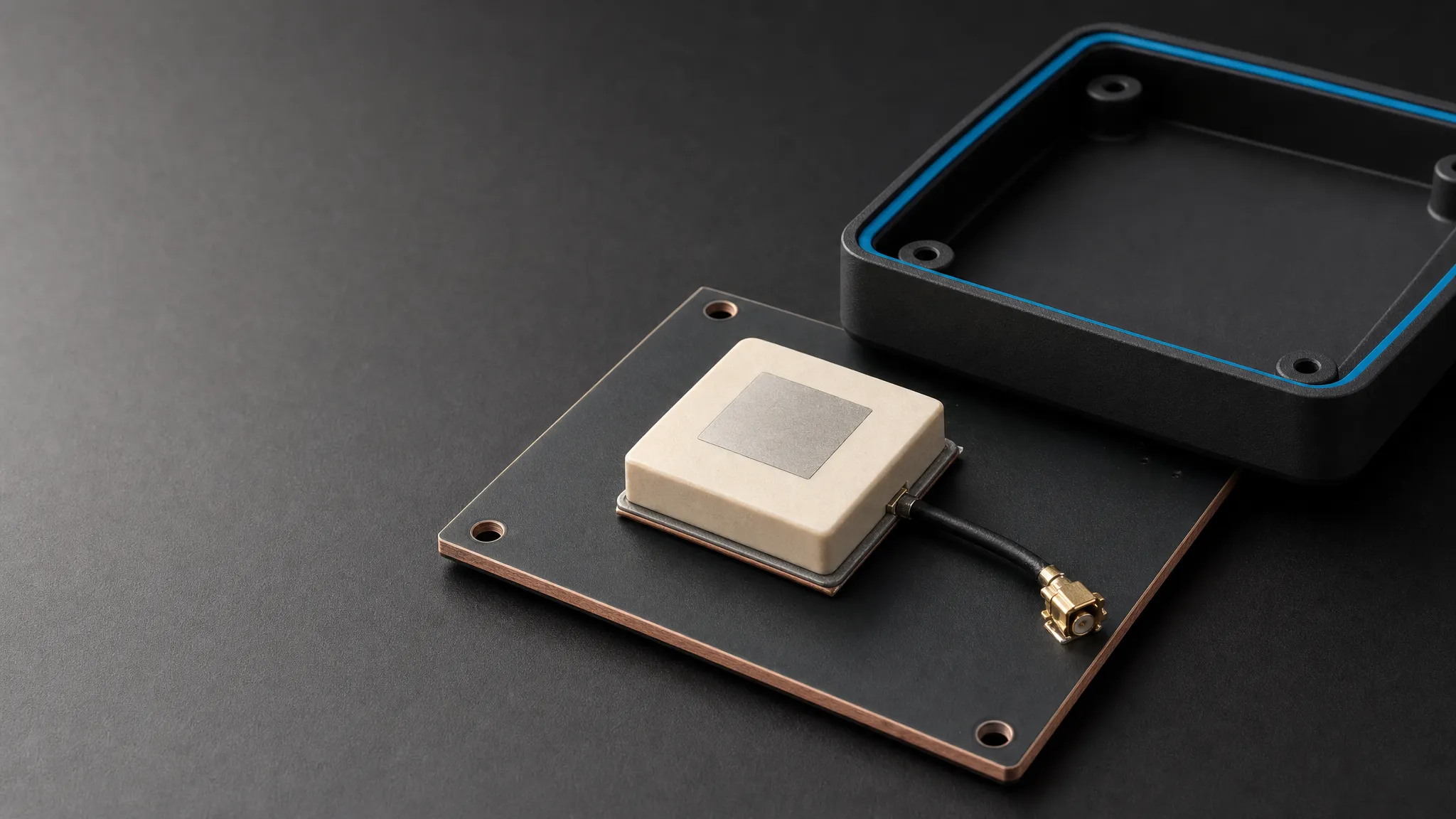
| Patch assembly | Low profile and integration into a board, module or enclosed survey antenna | Required ground plane, enclosure effects, band-specific patterns and calibration |
| Helical assembly | A possible fit when the available footprint and platform attitude favor its pattern | Height clearance, orientation, installed response, supported signals and phase behavior |
This table is a shortlist guide, not an accuracy ranking. A calibrated survey antenna can use a patch-based design. A compact helix can still perform poorly if the airframe blocks it or the receiver lacks the required corrections.
u-blox’s GNSS antennas application note, R03 (2019) explains why ground-plane size and placement need to be checked for the chosen element design. Treat the complete assembly as the item under evaluation.
What a choke ring changes
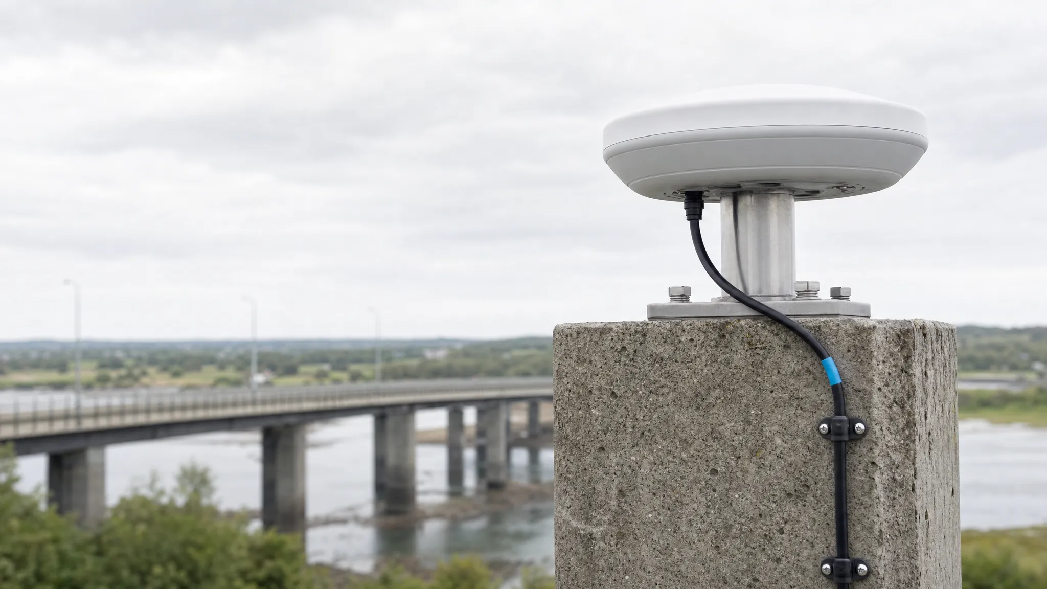
Concentric conductive structures around the element can reduce reception of some reflected signals, particularly those arriving from below the horizon. This makes choke ring assemblies candidates for permanent reference and monitoring sites where their size and mounting load are manageable.
The structure cannot remove every reflection. Signals reflected from a nearby roof or mast can arrive from the upper hemisphere. Nor does a choke ring supply the receiver, correction service, reference coordinates or observation model that the positioning workflow needs.
Ask for patterns on the frequencies you will use and for the calibration identity of the supplied antenna and radome. A result for one antenna at one elevation is not a universal rejection figure for the entire design class. For a reference-network purchase, check whether the intended network accepts the configuration before ordering.
A patch is not automatically a low-precision antenna
A patch’s behavior depends on its geometry, feed, ground plane and surroundings. A bare ceramic element on a development board is a different product from an enclosed multiband survey assembly with characterized phase behavior. Comparing them by the word “patch” hides the differences that matter.
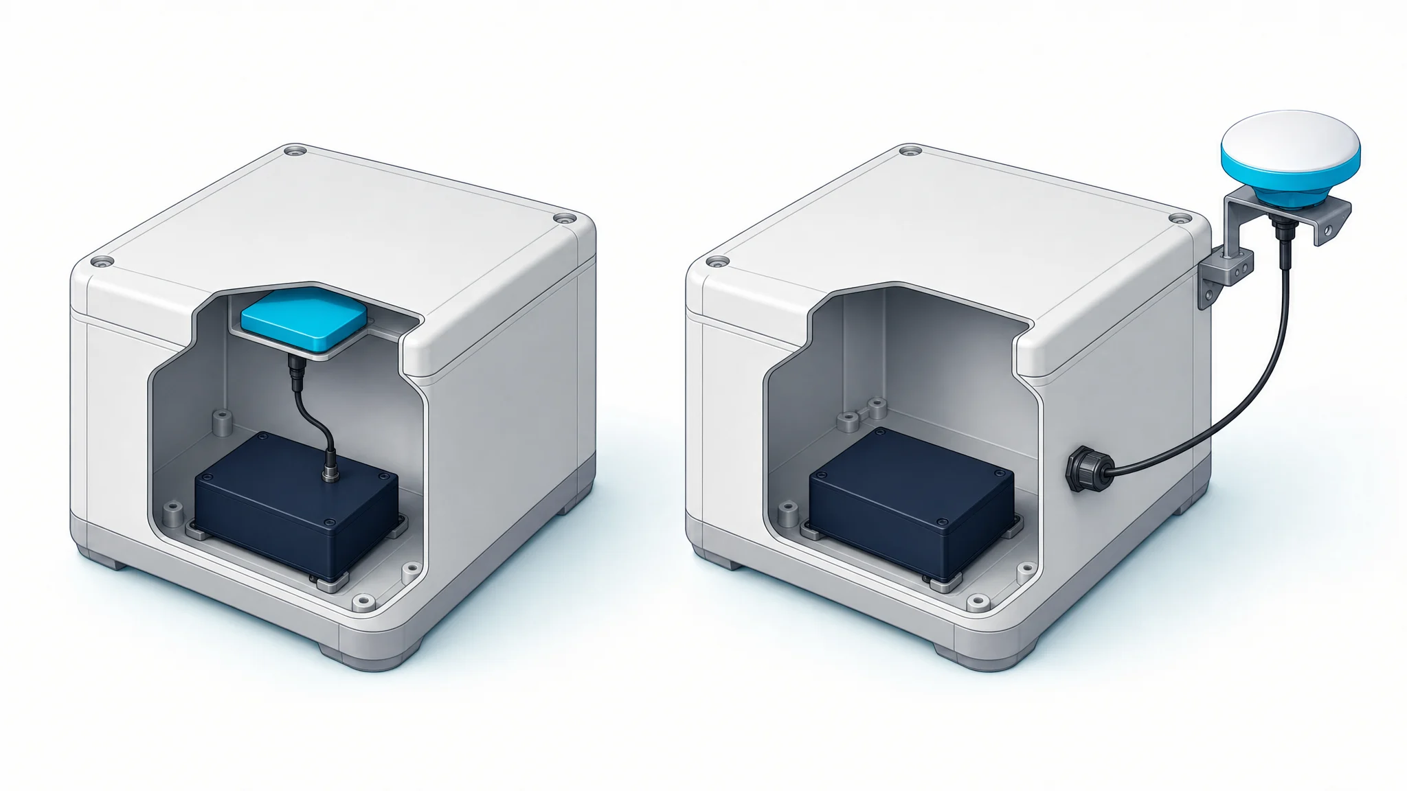
For an embedded installation, obtain the manufacturer’s ground-plane and keep-out recommendations. Test the final board, battery, enclosure and cable arrangement together. A larger metal plate is not automatically an improvement: it changes the antenna environment and needs evaluation.
Low profile may make a patch assembly easier to package on a vehicle roof or inside a receiver. That mechanical benefit does not determine its achievable positioning result. Select the model using band coverage, installed pattern and calibration evidence appropriate to the job.
A helical design still needs an installation test
Helical antennas can offer useful circular polarization and patterns for mobile equipment. Their height and orientation also affect packaging, impact exposure and shadowing. Some configurations rely less on an external ground plane; that is a model-specific property, not permission to ignore the mounting instructions.
Do not assume a helix keeps a constant electrical phase center when tilted. Platform rotation changes the satellite directions seen by the antenna, and nearby materials can change the pattern. Compare tracking and phase observations over the attitude range of the actual mission.
For a drone, test turns and pitch changes as well as level flight. For a rover, include the pole, operator and nearby equipment. A result from an isolated antenna does not fully describe either installation.
Compare phase-center evidence on equal terms
Separate phase-center offset, direction-dependent variation and the physical antenna reference point. A brief “phase center error” line in a datasheet does not establish a complete calibration model or its uncertainty.
The NGS antenna calibration service identifies antenna types with an antenna code and radome code. That level of identity is more useful for a precise survey workflow than a claim that one shape is inherently accurate. Our GNSS antenna calibration and ANTEX guide walks through the record-to-hardware match.
Do not turn a calibration value into a system accuracy promise. Site multipath, receiver processing, corrections, observation duration and reference information remain part of the result.
A fair evaluation before purchase
Define the receiver, firmware, tracked signals, corrections and cable path first. Then record the antenna configuration and its reference point so that comparisons do not accidentally include different heights or offsets.
For each candidate, evaluate:
- Tracking by signal and elevation, including interruptions and cycle slips.
- Fixed and float solution periods, with correction age and outages identified.
- Position errors against an independent reference where the application requires them.
- Behavior in the final mounting position, including nearby reflectors or platform motion.
- Mechanical fit, environmental evidence and replacement requirements.
Use repeated observations because satellite geometry and the environment change. Keep a quiet baseline as well as the difficult part of the route. If multiple parts change together, the result describes the new installation; it does not prove the antenna shape caused the improvement.
For an RFQ that compares complete models, use the high-precision GNSS antenna selection guide. Send GNSource your receiver, signal list, mounting drawing and calibration requirements when you request an antenna review; those details support a useful shortlist without assuming a form factor guarantees accuracy.