GPS and BeiDou projects
For a receiver project using GPS and BeiDou, include the required signals in your antenna inquiry. Compare them with the two listed frequency points before reviewing the mechanical installation.
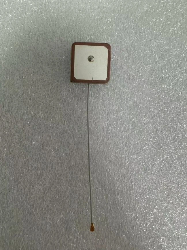
Ceramic patch antennas
A ceramic patch antenna assembly for GPS and BeiDou, with a coaxial lead.
WL-GPSI25254-100: 1561.098 MHz / 1575.42 MHz. This ceramic patch assembly brings GPS and BeiDou frequency requirements into the same model discussion. Start with the signals your receiver will use, then review patch placement, the coaxial connection and the enclosure layout. When comparing it with the other WL-GPSI models, use the listed frequency points and installation format rather than assuming that two products with a similar shape cover the same requirements.
| Frequency | 1561.098 MHz / 1575.42 MHz |
|---|---|
| Impedance | 50 Ω |
| Polarization | RHCP |
| VSWR | ≤2 |
| Connector family | I-PEX / IPEX |
| Operating temperature | −40°C … +85°C |
Planning a positioning product? Use the project examples below to define the receiver, antenna location and connection you need.
For a receiver project using GPS and BeiDou, include the required signals in your antenna inquiry. Compare them with the two listed frequency points before reviewing the mechanical installation.
For a tracking device with an internal patch antenna, describe the receiver, housing and coaxial path together. Include nearby cellular or other radio hardware so the overall layout can be reviewed.
Provide the receiver model and required signals. Review the antenna connection and receiver antenna-port requirements together with the frequency selection.
Share the intended antenna orientation, enclosure material and nearby metal parts. Evaluate reception in the assembled device, including its normal operating position.
Include the board layout and ground-plane arrangement in the installation review. Keep nearby electronics and radio transmitters in the same drawing rather than reviewing the antenna in isolation.
Specify the exact mating connector and required cable route. Allow access for assembly and include the space needed for the connection when checking the installed envelope.
Start with the receiver’s required frequencies, then compare the antenna format and the space available inside your device.
Compare the square GPS patch layout with your antenna location, board connection and cable access.
Compare the square GPS patch layout with your antenna location, board connection and cable access.
Compare a narrow rectangular GPS format when your planned antenna area is elongated rather than square.
1561.098 MHz / 1575.42 MHz. Start with the signals required by your receiver. Share its model and signal list with your inquiry so frequency coverage can be matched to the antenna selection.
Send the mating connector part number or a clear board-connector drawing, together with the required cable route. The I-PEX / IPEX family name alone does not identify the exact mating pair.
Review antenna orientation, nearby metal, the board and cable access together. Assess reception with the device assembled in its intended operating position, not only with the antenna on a bench.
Include the antenna model, receiver, required signals, installation drawing, connector and cable requirements, and evaluation or order quantity. Add your target schedule so the team can discuss the project with you.
Get a Quote
Tell us the antenna model, receiver, required frequencies, connector and cable requirements, and order quantity to request a quote.